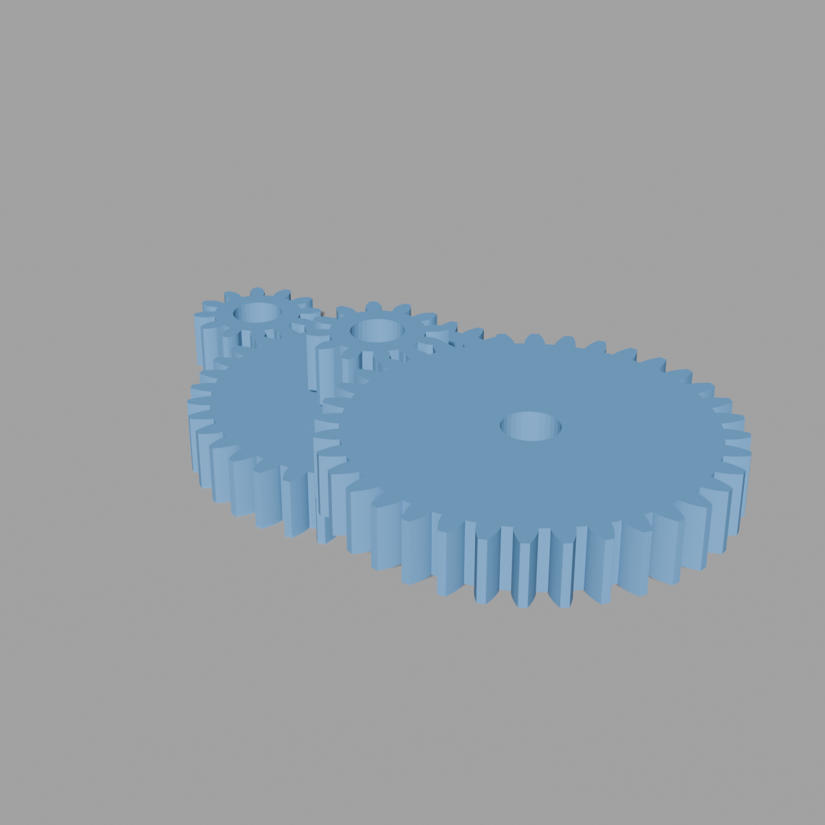
gears/external/compound_gear.py → OBJECT_OT_add_compound_gear (object.add_compound_gear, "Add Compound Gear")
Builds a full multi-stage gear train — up to 4 stages, each a driver/driven pair on a shared intermediate shaft, auto-positioned so each stage's pitch circles are tangent along X. Self-contained like the other gear-set primitives — no stamp_gear, no Match Target. See README.md for family-wide conventions.
Properties
| Property | Type | Default | Range | Notes |
|---|---|---|---|---|
stage_count | Int | 2 | 1–4 | |
s1_driver … s4_driver (labeled "Driver Teeth") | Int | 12 (all stages) | 4–200 (soft) | Per-stage driver tooth count |
s1_driven … s4_driven (labeled "Driven Teeth") | Int | 36, 36, 24, 24 | 4–200 (soft) | Per-stage driven tooth count |
module | Float (mm) | 1.0 | 0.1–50.0 | Shared by every gear in the train |
pressure_angle_deg | Float (°) | 20.0 | 10–45 | |
width_mm | Float (mm) | 6.0 | 0.5–50 (soft) | Shared by every gear |
bore_enable | Bool | True | ||
axle_hole_mm (labeled "Bore Ø") | Float (mm) | 5.0 | 0.1–50 (soft) | |
axle_compensation_mm | Float (mm) | 0.2 | 0.0–1.0 (soft) | Added to hole radius |
parent_under_empty | Bool | True | Parents all created gears to a new Empty |
All 4 stages' driver/driven properties share identical labels in the UI ("Driver Teeth" / "Driven Teeth") — they're distinguished only by which per-stage box they appear in, and internally by property name (s1_driver…s4_driver, s2_driven…s4_driven).
Ratio math
Per stage i: ratio_i = driven_teeth_i / driver_teeth_i (step-down when
1). Overall train ratio is the product of every active stage's ratio.
Center distance per stage is module*(driver_teeth + driven_teeth)/2, and stages are laid out end-to-end along X: each stage's driver sits where the previous stage's driven gear ended.
The panel shows each stage's own ratio ("Stage %d — 1 : %.3f") plus the overall ratio and total X span.
Z layout is a display convention, not a physical shaft offset
Each stage occupies its own Z plane, offset from the previous stage by width_mm + STAGE_GAP_MM (STAGE_GAP_MM = 1.0). This exists purely so the whole train is visually inspectable in the viewport — a real compound gear train's stages don't literally sit at different Z heights the way this generator draws them; within a single stage, its driver and driven gear genuinely do share one shaft and one Z plane (mesh along X, pitch circles tangent), but the gap between stages is a display simplification, not a claim about how you'd actually build the shafts.
Bore safety check
Same pattern as cluster_gear.md: the minimum dedendum radius is computed across every driver/driven tooth count in every active stage, and if bore_r >= min_dedendum, the panel shows "Axle hole too large — max Ø %.2f mm for smallest gear" (ERROR-icon, non-blocking).
Build method
Reuses spur_gear.build_gear_profile() for every gear (like cluster_gear, unlike the planetary-set files). Each gear is its own solid object (_build_solid_gear) — unlike cluster_gear's fused single mesh, there's no shoulder-bridging here, and unlike the planetary sets' boolean bore, the bore hole here (when enabled) is built directly into the same bmesh as annular top/bottom faces via triangle_fill, not as a separate boolean cutter object.
Naming and object count
2 * stage_count gear objects per call, plus one optional parent Empty if parent_under_empty is True (default 4 gears + 1 empty at the default stage_count=2):
- First stage's driver →
GearInput - Last stage's driven →
GearOutput - Every other driver/driven →
GearS%dDriver/GearS%dDriven
If parent_under_empty, all gears are parented to a new CompoundGear empty (PLAIN_AXES, sized to max(total_span*0.1, 5.0)), with matrix_parent_inverse set so parenting doesn't move anything.
Success message: "Compound gear: %d stage%s, 1 : %.3f overall ratio". Straight teeth only — no hand, no helix, no boolean bore cutters anywhere in this generator.